Electrical System Design
With instrument panel technology currently moving like a piano down a lift shaft, it's scary to commit money to any particular system in case it's immediately superseded by something better, faster and cheaper. For that reason it's wise to leave selection of the various instruments and avionic components to the last possible moment. However, you do need to plan ahead.
For my own particular circumstances, a Vans RV-7 and either 180hp or 200hp Lycoming engine, I can take advantage of the excellent Vans Firewall forward kits. It's not plug and play, but comes with practically everything I need to get the fan at the front of the aircraft working. Even without detailed instructions there's plenty of online advice, scattered through a plethora of builders websites, on everything from baffles to firewall penetrations.
As daunting as it seems to a tyro builder, and save some notable exceptions, the installation of the stock engine seems one of the more straight forward aspects of the build. The instrument panel components on the other hand come with no instructions save an operation manual, and normally a electrical diagram. All connections need to be made by the builder, as does correct wire and fuse/circuit breaker selection. With many sources of interference (both physically and electrical) the builder is far more hands-on in the design process.
I figure, and it's open to debate, that I've reached the stage (mid fuselage build) that I need to start seriously planning both the instrument panel design and aircraft electrical system. Of all the things left, bearing in mind I'm not even halfway through the build, nothing else has more effect on everything else than the wiring.
The electrical system I'm installing will be based on Bob Nuckolls' Aero-Electric Connection. Now whether you're a fan of his writing style or not, he does put forward some good ideas on reliability and having read and reread the Connection, I'm falling into line and following his preaching to almost the letter with a split buss, single battery/twin alternator system.
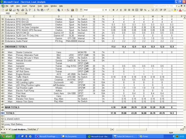
The first stage of the design is to conduct a detailed load analysis. Simply the sum of a electrical demand on the aircraft in various portions of flight, it forms the basis of the gospel according to St Nuckolls; "System reliability is optimal when I can suffer any of the most common failures and still put the wheels on the ground, at my intended destination, without breaking sweat."
By knowing exactly how much electrical energy my aircraft will consume in any particular configuration I can, with the help of the Aero-Electric Connection, optimise the electrical system to enable me to have the final decision on if, how or where I want to continue the flight to in the event of an electrical failure. You're load analysis can be as simple or as complicated as you want, I shameless copied an Excel program from another builder; technophobes just resort to paper. [Click here to open Electrical Load Analysis Excel file]
My electrical system is split into three busses; battery, main and endurance. Pretty self explanatory, and in the extreme worst case scenario of operating everything single thing in the aircraft at the exact same time; she draws 45amps. However, the essential "endurance buss" for cases of alternator or battery failure requires only 8amps. For that I retain full dual EFIS, GPS, NAV/COM, Transponder, Audio panel and Angle Of Attack capabilities, alongside retaining electronic ignition.
A single standard fit PC680 Odyssey 16amp hour battery, should then, in theory, be able to support 1 hour of flight. To further increase reliability I decided to fit twin alternators, a main and standby. The main alternator, a B&C L-60, cranks out 60amp, whilst the standby SD-20, produces close to 20A. So in the case of any single alternator failure I'd still have enough electrical energy to continue the flight until the tanks run dry... which is the whole idea behind Nuckoll's designs - maximise what you've got.
Having completed the load analysis, and selected a single battery/twin alternator design I began putting in a lot of time on TurboCad, getting my electrical schematics done. Due to my complex EFIS system, and lots of electrical goodies, switches and indicators I decided it was probably worth my time bastardising one of Nuckolls' standard schematics, in my case Z-13/20.
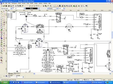
Below are listed my various electrical schematics, just remember they're still a work in progress. If you don't have TurboCad; download the PDF version for display on a free Adobe reader. Usual disclaimer: I take no responsibility for the accuracy of these diagrams, follow them at your own risk.
|
|
TurboCad Deluxe v11 |
|
| Figure D-1 Master Electrical Diagram | Figure D-1 (123kb) | Figure D-1 (552kb) |
| Figure D-2 Ignition System | Figure D-2 (54kb) | Figure D-2 (145kb) |
| Figure D-3 Starter Circuit | Figure D-3 (42kb) | Figure D-3 (92kb) |
| Figure D-4 Flap Positioning System | Figure D-4 (39kb) | Figure D-4 (82kb) |
| Figure D-5 Trim System | Figure D-5 (47kb) | Figure D-5 (106kb) |
| Figure D-6 Fuel Boost Pump | Figure D-6 (48kb) | Figure D-6 (95kb) |
| Figure D-7 HID Landing Lights | Figure D-7 (44kb) | Figure D-7 (70kb) |
| Figure D-8 Panel CAD Layout | Figure D-8 (74kb) | Figure D-8 (291kb) |
| Figure D-9 Seat Heaters | Figure D-9 (47kb) | Figure D-9 (71kb) |
| Figure D-10 Battery Buss | ||
| Figure D-11 Main Buss A & B | ||
| Figure D-12 Endurance Buss |